From Gate-All-Around to Complementary FETs: What's Next in Transistor Scaling — 中文解读
Synopsys 梳理从 FinFET→GAA→CFET 的晶体管缩放路径,探讨背面供电与 DTCO 两大赋能技术,及 AI 时代的功耗压力。
来源:Synopsys Blog — From Gate-All-Around to Complementary FETs: What’s Next in Transistor Scaling 原文链接:https://www.synopsys.com/blogs/chip-design/gate-all-around-complementary-fets-whats-next-transistor-scaling.html 原文发布日:2026-08-18 | 作者:Ravi Todi、Urmimala Roy、Xi-Wei Lin(Synopsys) 说明:本文为英文原文全文转载,附中文结构化解读。原文以英文写就,未作翻译;解读部分为整理归纳,不代表原作者观点。
第一部分:正文(Original Article)
By Ravi Todi, Urmimala Roy, Xi-Wei Lin
Introduction
Two years ago, we introduced why the industry was moving to gate‑all‑around (GAA) transistors and how foundation IP co-optimized with electronic design automation (EDA) flows would be key to success. Since then, GAA has moved from early adoption into the mainstream of leading‑edge design, and the industry’s attention is already turning to what comes after it. This article revisits where GAA stands today and looks ahead to its successor, the complementary FET (CFET).
For several decades, semiconductor industry growth has followed “Moore’s law” [1], with the number of transistors doubling roughly every two years. Initially, the transistors were planar structures. Moore’s law meant that transistors continued to be smaller in dimensions, so planar transistors soon proved inefficient in controlling the flow of charge in the channel and FinFETs were introduced [2]. The “fins”, semiconductor channels protruding out of the wafer in the out-of-plane direction, have the gate covering the channel on three sides, giving the gate better electrostatic control of the channel than planar FETs. They, however, had a challenge of their own. The current carrying capacity of the transistor is proportional to the number of fins (which act as “parallel channels” between the source and the drain). That makes the effective width of the transistor quantized (in steps of fin number and associated space in the layout). Also, as FinFETs kept scaling down towards the ~3nm node, they became less efficient as an electrical switch. Near the bottom of the fin, closer to the substrate, gate control weakens, making the area susceptible to leakage. Furthermore, FinFET transistor variability increases as scaling continues, making it less suitable for 2nm node and beyond.
GAA Today: Where the Technology Stands
Beginning at around the 2nm node, the industry started transitioning to a new transistor architecture, gate-all-around (GAA). In GAA, there are nanosheets of semiconductors with the gate wrapping around them on all four sides (Figure 1), which lets the gate voltage control the charge in the channel more effectively than a FinFET.
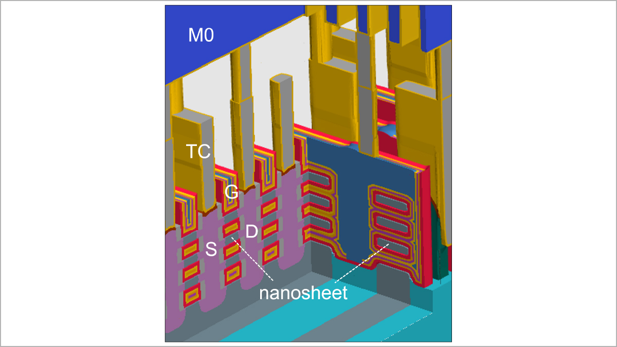 图01|原文配图(Synopsys)
You can see the gate’s stronger grip in a steeper sub-threshold slope (SS), which translates to a higher Ion/Ioff ratio (a transistor, as a switch, will carry the current Ion in its “on” state and the current Ioff, when in the “off” state). GAA offers better electrostatic control and hence the steeper SS. Another advantage of GAA is that the channel thickness is better controlled in the manufacturing process, leading to smaller device variations.
GAA can also be thought of as fins flipped sideways and then stacked vertically. That makes the width continuous in the plane of the layout [3], allowing the process to be optimized using the nanosheet width as a variable. In effect, nanosheet width becomes a knob designers can turn to balance performance against area (Figure 2). Wide transistors help achieve high performance in a standard cell owing to higher current carrying capability, which makes high-performance standard cells ideal for high-performance computing. Conversely, narrow transistor width can be used for high-density, low-power standard cells, which are better suited to battery-powered mobile applications [3].
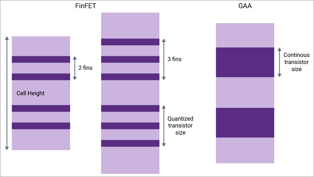 图02|原文配图(Synopsys)
It’s worth noting that planar, FinFET, and GAA devices are each likely to keep playing a role: not every system-on-chip (SoC) function needs to be implemented in the most advanced node, and heterogeneous, multi‑die designs increasingly bring these transistor types together in a single product.
Why GAA Is Critical in the AI Era
An important implication of transistor scaling is that each subsequent node consumes less power than its predecessors. Right now, the semiconductor industry’s growth is fueled by the artificial intelligence (AI) “revolution”. With the introduction of large language models to a broader audience in 2022, the user base of AI tools has grown exponentially. Training such models requires a huge amount of computation, which, in turn, needs specialized hardware such as GPUs, often sitting in large data centers. It is predicted that, at the current rate of growth, data centers will consume ~7-8% of global electricity demand sometime around 2030 (Figure 3) [3, 4]. That kind of power draw puts real pressure on the global electricity infrastructure, and it’s a big reason the industry is so focused on designing chips that consume less power. This makes GAA (and its successor transistor geometries) particularly important in the AI era.
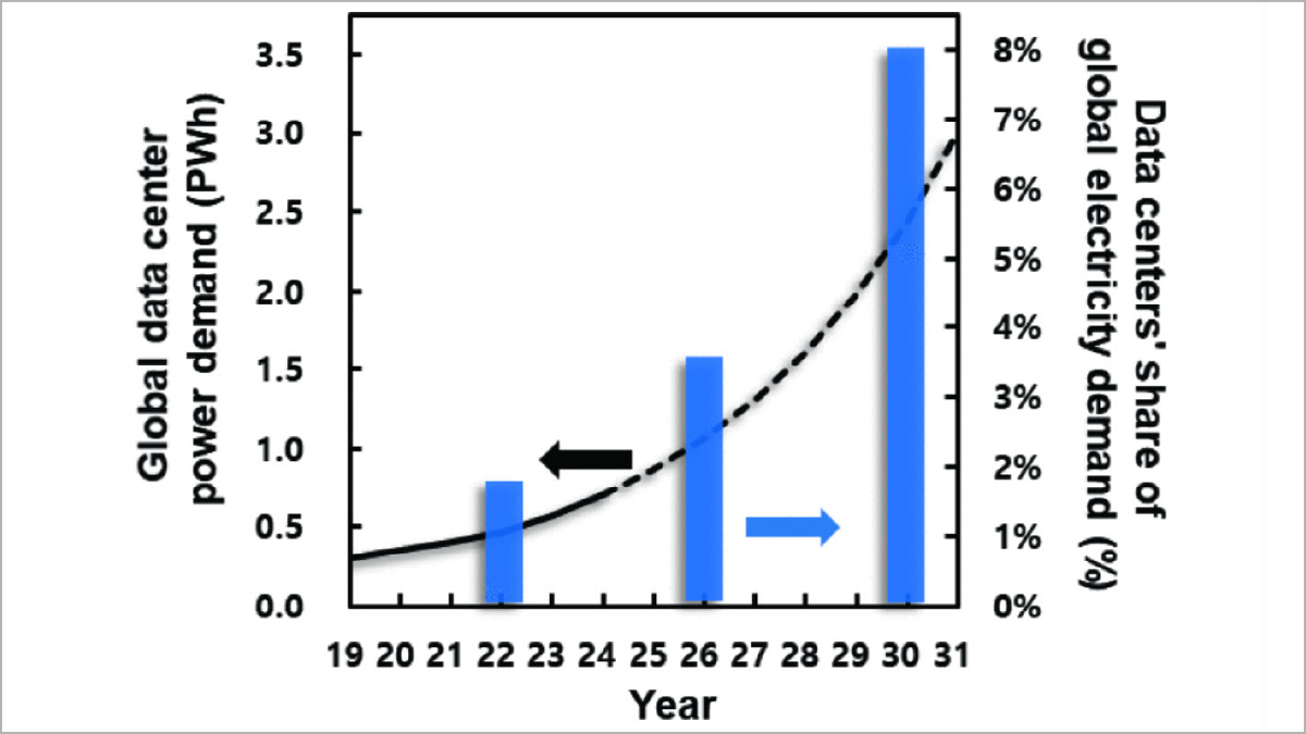 图03|原文配图(Synopsys)
Today, high‑performance mobile is leading GAA adoption, with hyperscale servers and high‑performance CPUs following closely behind—a clear shift from the early‑adoption picture of just two years ago.
Two Enablers: Backside Power and DTCO
Two key technology innovations are helping realize the full benefits of GAA transistors at advanced nodes:
- Backside power delivery: Traditionally, the transistors are built first, then many layers of metal are stacked on top to route power and signals between them. As dimensions shrank, routing became harder, with signal and power competing for space. In recent years, foundries have begun separating power and signal delivery to the transistor from two opposite sides of the transistor layer. This frees up more space for both and makes routing easier. With backside power delivery, bulk silicon no longer sitting beneath the transistors to carry heat away, so self-heating becomes a challenge to manage.
- Design technology co-optimization (DTCO): Standard cells and static random-access memories (SRAMs) take up most of the area inside a system on a chip (SoC) [5], so they largely determine its power, performance, and area (PPA). Beyond reducing the dimensions that impact cell area—such as contacted poly pitch (CPP), gate length, and metal pitch—advanced nodes require optimizing many other aspects to achieve desired PPA, including co-optimization with advanced EDA tools [5]. A technology can be optimized for PPA at multiple levels: gate length, poly pitch, and metal pitch at the first level; then gate cross-coupled structures and diffusion breaks; then optimizing for place-and-route access for the pins; and ultimately, at the block level [5].
How Synopsys Helps Design Teams Make the Leap
Realizing these benefits in a real SoC depends on high‑quality IP and EDA flows that are co‑optimized for the target process—the same point we made two years ago, and it holds even more true today. Drawing on a 20‑year history of developing Foundation IP across the planar and FinFET eras, and on work with hundreds of customers, Synopsys 2nm GAA Foundation IP is being delivered to customers today, co‑optimized with Synopsys EDA flows to enable the most area-optimized designs, and, ultimately, the lowest total cost of ownership at advanced nodes. Synopsys’ technology computer-aided design (TCAD) tools help in technology development and DTCO by enabling simulation of electrical/thermal characteristics of transistors at the advanced node geometries, including GAA and CFET. On the EDA side for physical implementation, the Synopsys Fusion Design Platform™ (an integrated, golden‑signoff RTL‑to‑GDSII flow) has been qualified for GAA process technologies at major foundries. In addition, Synopsys has collaborated with foundries to optimize our AMS Design Reference Flow, based on Synopsys Custom Design Platform, for the GAA process. As the industry moves toward CFET and angstrom‑scale nodes, this same IP‑plus‑EDA co‑optimization is what will let design teams hit ever more demanding PPA targets.
What’s Next: The Move to CFETs
The unprecedented demand for semiconductor chips driven by the AI “revolution” calls for continued device scaling to enable lower power consumption, smaller chip area, and faster chips. Two years ago, we noted that CFETs were on the horizon; today they have moved from concept to demonstrated silicon. Beyond GAA, the next generation of transistors is expected to be CFETs, where the NMOS and PMOS are stacked vertically (Figure 4), shrinking footprint and increasing transistor density.
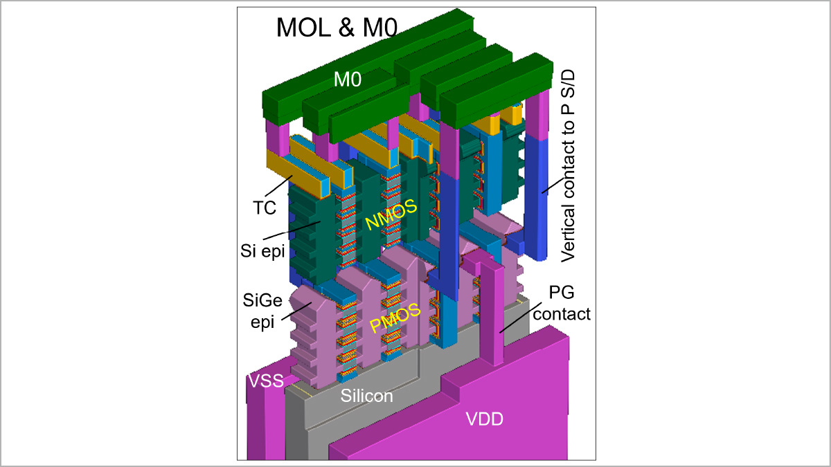 图04|原文配图(Synopsys)
Recently, researchers demonstrated working ring oscillators and SRAM cells built with CFETs [6]. As with GAA technology, DTCO will be an important part of PPA optimization for CFETs [6]. Recent work demonstrated 3.5-track CFET designs in A7 (7 Å technology equivalent) reaching 46% area reduction compared to their N2 (2nm technology equivalent) reference, while keeping performance the same [7]. Potentially combined with backside power delivery and with the growing role of multi‑die, chiplet‑based design, CFET is poised to be the next step in extending scaling into the angstrom era.
Learn more about our Synopsys Foundation IP solution
References
- R.R. Schaller, “Moore’s law: past, present and future,” IEEE Spectrum, vol 34, no.6, pp. 52-59, 1997.
- D. Hisamoto et al., “FinFET—a self-aligned double-gate MOSFET scalable to 20 nm,” IEEE Transactions on Electron Devices, vol. 47, no. 12, pp. 2320–2325, Dec. 2000, doi: 10.1109/16.887014, 2000.
- W. Kwon et al., “Gate-All-Around Technology for Sustainable AI: A Foundation for Future Logic Architectures,” in 2025 IEEE International Electron Devices Meeting (IEDM), San Francisco, CA, USA, pp. 1-4, 2025.
- IEA, Electricity 2024: Analysis and Forecast to 2026, Paris, France: International Energy Agency, 2024.
- T. Song et al., “3nm gate-all-around (GAA) design-technology co-optimization (DTCO) for succeeding PPA by technology,” in 2022 IEEE Custom Integrated Circuits Conference (CICC), 2022.
- S. Liao et al., “First demonstration of CFET ring oscillator and SRAM bit-cell functionality at gate pitch smaller than 48 nm for future logic and SRAM technology,” in 2025 IEEE International Electron Devices Meeting (IEDM), 2025.
- J.Y. Lin et al., “3.5T CFET Block-Level DTCO for Superior PPA in A7 Node by Split Power, hDR Cells, Optimized Pins and BEOL,” in 2025 IEEE International Electron Devices Meeting (IEDM), 2025.
第二部分:解析(深度解读)
以下为基于原文的结构化中文解读,仅供学习交流,不代表原作者观点。
一、这篇文章在讲什么
Synopsys 三位作者(Ravi Todi、Urmimala Roy、Xi-Wei Lin)系统梳理了晶体管从平面 → FinFET → GAA(环绕栅极)→ CFET(互补 FET)的缩放路径。文章有两层重点:一是 GAA 为何在 2nm 节点成为主流(相比 FinFET 更好的静电控制、连续可调的沟道宽度);二是在 AI 功耗压力下,GAA 之后由 CFET 接棒——NMOS 与 PMOS 垂直堆叠,进一步压缩面积、提升密度。文中还点出两大「赋能技术」:背面供电(backside power)与 DTCO(设计-技术协同优化),并借机展示 Synopsys 在 GAA/CFET 上的 IP+EDA 组合拳。
二、关键概念拆解
- FinFET 的天花板:鳍数决定有效沟道宽度(量子化),底部栅控弱→漏电,变异性随缩放恶化,~3nm 后不再合适。
- GAA / 纳米片:栅极四面包裹纳米片,亚阈值斜率更陡、Ion/Ioff 更高;纳米片宽度成为「性能 vs 面积」的可调旋钮。
- 背面供电:把供电与信号从晶体管层两侧分开走线,缓解布线拥塞;代价是失去体硅导热→自热成为新挑战。
- DTCO:标准单元与 SRAM 占 SoC 大半面积,决定 PPA;先进节点要在栅长/多晶间距/金属间距之外,做多层协同优化。
- CFET:NMOS/PMOS 垂直堆叠(图4),A7 节点 3.5-track 设计相对 N2 参考降面积 46% 而性能不变;已演示环形振荡器与 SRAM 单元。
三、与本站其他文章的衔接
- 先进封装 / 多 die:文中强调平面/FinFET/GAA 长期共存,异质多 die 设计把多种晶体管类型塞进同一产品——与本站先进封装系列(EMIB vs CoWoS 等)呼应。
- AI 硬件 / 功耗:「数据中心 2030 年或占全球用电 7-8%」是 AI 时代制程缩放的根本驱动力,与本站 AI 硬件/推理芯片系列同频。
- CPO / 光互联:逻辑算力缩放的尽头仍是「数据怎么搬」;前端晶体管的能效提升,最终要和光互连的带宽墙叙事合流。
四、趋势与投资映射
- 制程叙事从「线宽竞赛」转向「晶体管架构 + 供电 + DTCO + 多 die」的系统工程;EDA 与 IP 在先进节点的话语权上升(Synopsys/Cadence 直接受益)。
- 背面供电、CFET、angstrom 节点是设备/材料/代工的新增量:相关刻蚀、外延、键合、背面处理设备与 EDA 签核工具链值得跟踪。
- 风险:CFET 仍处「演示硅」阶段,3.5-track 良率、自热、协同设计复杂度都是不确定性;AI 算力需求若放缓,先进节点资本开支节奏会受影响。